Technical Specifications
The Harmonic Filter is an inductive device that does 2 things. First, it removes 'noise' (that results from incoming voltage legs being out of balance) or harmonic distortion from the broad band spectrum of harmonics, including 5, 7, and 9th harmonics. Second, the inductive qualities provide a restoration of phase and polarity to the electric circuit.
The property of inductance is described as “when any piece of wire is wound into a coil form, it forms an inductance which is the property of opposing any change in current." Alternatively, it could be said “inductance is the property of a circuit by which energy is stored in the form of an electromagnetic field."
A piece of wire wound into a coil form has the ability to produce a counter emf (opposing current flow) and therefore has a value of inductance. The standard value of inductance is the Henry, a large value which is like the Farad for capacitance is rarely encountered in electronics today. Typical value of units encounter are milli-henries (mH), one thousandth of a henry or the micro-henry (uH), one millionth of a henry. A small straight piece of wire exhibits inductance, probably a fraction of uH although not of any major significance until we reach UHF frequencies.
The value of an inductance varies in proportion to the number of turns squared. If a coil was one turn, its value might be one unit. Having 2 turns the value would be 4 units while 3 turns would produce 9 units although the length of the coil also enters the equation.
FORMULA - Imperial (non-metric) measurements
L=r squared X N squared / (9r+10len)
Where: L = inductance in uH; R = coil radius in inches; N = number of turns; Len = length of coil in inches
Electric System Topology

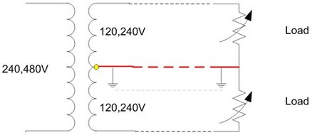
Typical Single Phase Power Distribution
Notes
Notes
- Only true “ground” is at the center tap of the transformer (yellow dot)
- The “earth” and the neutral line form a parallel path (grey + red line)
- Most return current not flowing through and opposing phase flows through the neutral as the earth is relatively high impedance
Loads and the Harmonic Filter

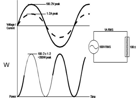
Resisitive (Harmonic Filter has no Impact)

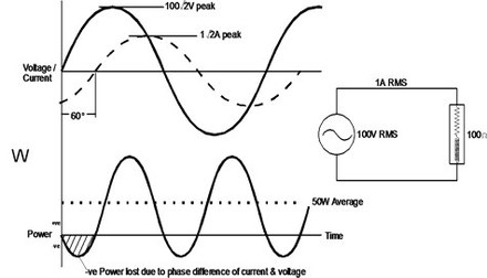
Inductive (Lagging Power Factor)

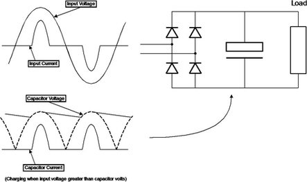
Rectified loads are Capacitive (Leading Power Factor)
All electrical systems are a combination of:
Capacitive – including AC to DC rectifiers
· Fluorescent Lighting Ballasts
· Laptop & Desktop computer power supplies (switching)
· VFD drivesVideo Game Consoles
· Screw in fluorescent lamps
Resistive
· Incandescent lamps, toasters, space heaters, etc.
Inductive
· Motors, compressors, fans, pumps
Harmonic Filter Loads and the Harmonic Filter Impact
Electrical "noise" in the CURRENT waveform appears on the neutral line – the neutral is the addition of the panel's phase currents.
· Most assume the neutral current is “Wattless”
· Neutral current is only “Wattless” if it is truly at “zero” voltage (correct polarity) with correct phase
· This is almost never the case
How does it work?
The Unit is an Inductor. Inductors change current into an electromagnetic field - field strength increases as current increases, and this field attracts certain frequency waveforms. VCG attracts the harmonic distorted waveforms.
· These waveforms include 3rd, 5th, 7th, 9th, 11th harmonics
· These waveforms are capacitive in nature
· It does not attract energy at the fundamental (60Hz)
· Waveforms outside the fundamental are commonly referred to as electrical “noise”
Given that the Harmonic Filter only works on neutral currents there is only value where neutral currents exist. Anything that puts noise on the neutral: fluorescent lighting ballasts, laptop and desktop power supplies (switching), VFD drives, video game consoles, screw in fluorescent lamps, etc.
The Harmonic Filter does not work on three phase delta-wired systems, perfectly balanced three phase wye systems, or 220 VAC loads with no neutral current.
Impact on THD & Power Factor
Harmonic Filter’s impact on Power Factor
· Improves capacitive (leading power factor) loads
· Limited effectiveness on inductive (lagging power factor) loads
· Improves distributed electrical system capacitance
Harmonic Filter’s impact on THD (Total Harmonic Distortion)
· Capacitive current noise component is filtered
· Electromagnetic field performs this function
Please call for Technical and Engineering Specifications - 800.933.0434.
Field Data shows savings in daily KWH range from 5 to 20+ percent. WAJA Lab data collected using their ANSI C12.20 class 0.5 revenue grade meter on an independent 3rd party test bench, shows 3 phase savings in daily KWH range from 5 to 7 percent on fluorescent lighting, HID lighting, and switch mode power supplies on computers.
Safety and Conformance Certifications
WAJA Labs testing the product using an A.N.S.I. C12.20 compliant test bench for revenue metering showed a 3.2-5% savings on switch mode power supply and computer loads. MET Labs© (Nation’s oldest NRTL as outlined in NEC©) tested and approved to UL-916 standards and CSA-C22.2 standards. Each model’s design certified by MET Labs. Dimensions and specifications subject to change without notice in accordance with our policy of continuous product improvement. Suitable for commercial and residential installation, requires measurable noise on the neutral. Product will not work on perfectly “clean” single or three phase loads – not suitable for delta-wired systems. Copyright© 2009 GiG2 Group, Inc. All Rights Reserved. Printed in U.S.A.
Harmonic Filter Specs
Featuring simple NEMA 3R weather proof design Field Data shows savings in daily KWH range from 5 to 20+ percent. WAJA Lab data collected using their ANSI C12.20 class 0.5 revenue grade meter on an independent 3rd party test bench, shows 3 phase savings in daily KWH range from 5 to 7 percent on fluorescent lighting, HID lighting, and switch mode power supplies on computers.
Installation Instructions included and WE RECOMMEND a Certified Electrician trained in our product do the installation for best results. Install 2 white wires to surround neutral returns on the neutral bus bar (cut white wires short). Install green chassis ground wire to panel ground bus. To insure proper installation, insure that the ratio of current flowing through the Harmonic Filter white wire to the current flowing through the main neutral bus is maximized.
Physical Characteristics
- Weight
- 3.2 pounds
- Size
- 4”X4”X2.5”
- Enclosure
